These are improved versions of a Halbach NMR Mandhala (along with several attachments) which have been updated in the summer of 2021 to be used in small magnetic resonance imaging experiments.
The purpose of the Halbach NMR Mandhala [Magnet Arrangements for Novel Discrete Halbach Layout, created by Raich and Blümler, “Design and Construction of a Dipolar Halbach Array with a Homogeneous Field from Identical Bar Magnets: NMR Mandhalas”, Concepts in Magnetic Resonance part B (Magnetic Resonance Engineering), Vol. 23B(1) 16-25 (2004), DOI 10.1002/cmr.b.20018] is to provide a large, homogeneous magnetic field over a large and accessible volume made from identical and affordable permanent magnets. This improved design uses longer magnets to provide stronger magnetic fields and more homogeneity along the central axis, aiming for samples that will roughly 1 cubic-centimeter in size. The permanent magnets used are still easily purchasable online.
This year’s design uses the same magnets as the previous Mandhalas to provide strong magnetic fields and homogeneity at the center of the bore.
Outer Mandhala
+ 4cm inner diameter; 8cm outer diameter
+ Letter-indicators for the north and south side of the Mandhala’s magnetic field.
+ Eight slots for 1⁄2” x 1⁄2”x 2” N52 magnets (K&J Magnetics: https://www.kjmagnetics.com/proddetail.asp?prod=BY088-N52)
+ Seven of the slots are 13.32 mm x 13.32 x 58 mm
+ One of the slots (at the North position) is 13.40 mm x 13.40 x 58 mm which makes it easier to insert the magnet given the strong resistance of the field at that point
- Tracks so the Inner Mandhala sits at the bottom of the rails so the middle of the Inner’s magnets are aligned with the middle of the Outer’s magnets
- A line inside that indicates the vertical location of the center of the magnetic field for measurement purposes
- Holes with an 8-mm diameter at the bottom of each slot
- A non-magnetic tool like nylon hex bolts can be inserted in the hole and used to easily push the magnets out of the slot and remove them.
Outer Mandhala accessories: + Frame for use with a modified XY removable microscope measuring stage. + Used to move the Mandhala around on the stage and take precise measurements with a stationary Gaussmeter. + Handle-lid with squares and snap-on brim to fit in the magnet holes more securely and with extended prongs to secure the Inner Mandhala. + More secure but doesn’t fit inside gradient in current form. + Has arrows to indicate the direction of the magnet’s magnetic field at that position. + Handle-lid with squares without snap-on brim to fit within gradient and with extended prongs to secure the Inner Mandhala. + Has arrows to indicate the direction of the magnet’s magnetic field at that position. + Lid for inserting magnets. + Lid only has one opening so the magnet being inserted can be placed.
Note:
The smaller slot openings are 0.62 mm larger than the magnet size, and the larger magnet slot is 0.7 mm larger than the magnet's size. This allows for easy insertion of the magnets, but it also makes it possible for the magnets to slide out of the slots when inserting them.
Inserting the magnets is therefore a two-person job; one person inserts the magnet into the slot, and another person holds the lid on to ensure that the magnets don't push it off and slide out. Then the lid is rotated to insert the next magnet and cover the slot where the last magnet was inserted. This helps prevent the magnets from flying out and pinching someone's fingers.
The magnets are strong and very fragile. When the magnets are not all inside the Outer Mandhala, we suggest using spacers to keep them from attracting each other and potentially breaking upon impact.
Inner Mandhala + 1.8cm inner diameter; 4cm outer diameter + Letter-indicators for the north and south side of the Mandhala’s magnetic field. + The “N” on the Inner Mandhala should face the same direction as the “N” on the outer Mandhala when inserting the Inner Mandhala into the Outer Mandhala so the magnetic fields are properly aligned + Eight slots for 1/4” x 1/4” x 1” N52 magnets (K&J Magnetics: https://www.kjmagnetics.com/proddetail.asp?prod=BX044-N52&cat=168) + All of the slots are 6.93 mm x 6.93 x 33 mm which makes it easier to insert the magnets + Rails on sides fit into rails on Outer Mandhala so the middle of the Inner’s magnets are aligned with the centers of the Outer’s magnets + The rails are 1.76 mm in width, 47 mm in length, and 37 mm in height + A line inside that indicates the vertical location of the center of the magnetic field for measurement purposes + Holes with an 4-mm diameter at the bottom of each slot + Used so a non-magnetic tool like wooden dowels can be used to easily push the magnets out of the slot and remove them.
The magnets are slightly loose in the slots to allow for easy insertion and removal of the magnets. However, this also results in the Inner Mandhala’s magnets being prone to flying out of the Mandhala while it is located in the Outer Mandhala.
Never remove the lid from the Inner Mandhala while it is inside the Outer Mandhala even if it is not being moved.
Always secure the lid whenever the Inner Mandhala is being inserted or removed from the outer Mandhala.
Inner Mandhala accessories: + Frame for use with a modified XY removable microscope measuring stage. + Used to move the Mandhala around on the stage and take precise measurements with a stationary Gaussmeter. + Handle-lid with squares. + Has arrows to indicate the direction of the magnet’s magnetic field at that position + Lid for inserting magnets. + Lid only has one opening so the magnet being inserted can be placed.
Note:
The magnet slot openings are 0.58 mm larger than the magnet size. This allows for easy insertion of the magnets, but it also makes it possible for the magnets to slide out of the slots when inserting them, or when removing the Inner Mandhala from the Outer Mandhala.
Inserting the magnets is therefore a two-person job; one person inserts the magnet into the slot, and another person holds the lid on to ensure that the magnets don't push it off and slide out. Then the lid is rotated to insert the next magnet and cover the slot where the last magnet was inserted. This helps prevent the magnets from flying out and getting broken.
The magnets are strong and very fragile. When the magnets are not all inside the Inner Mandhala, we suggest using spacers to keep them from attracting each other and potentially breaking upon impact.
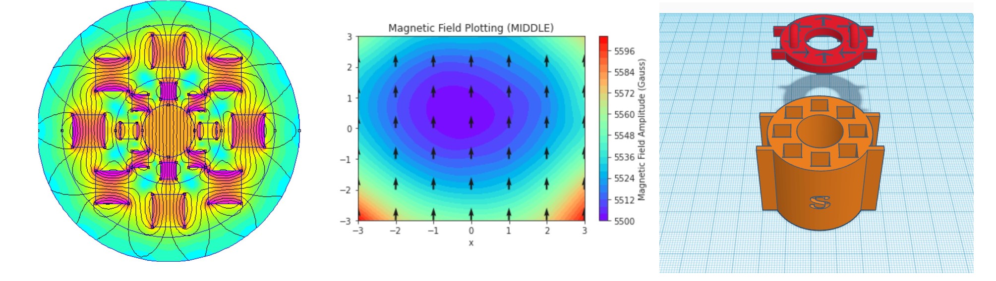
The magnets in both the Outer and Inner Mandhala should be oriented according to Raich and Blümer’s article (see photo in image above) to get a homogeneous magnetic field.
We found it useful to number our magnets by painting the bottom with liquid Wite-Out correction fluid then writing the number on them with a Sharpie after the paint dried.
This helps to keep track of which magnet is which before inserting them or when they are removed. Distinguishing between the magnets is important; while similar, they are not identical. The position of the magnets inside the Mandhala has been optimized using a genetic algorithm after measuring the magnetic strength of each.
Clear nail polish can help to protect the numbers from being rubbed off.
The stronger end of the magnets were marked as the “top” by using red nail polish to indicate the north side and blue nail polish to indicate the south side. This visual indicator helped when inserting the magnets into the Mandhala.
Click here to download the 3D print files on Thingiverse
These Mandhalas are an improvement on a previous design: (https://www.thingiverse.com/thing:3012509). All the files generated in TinkerCad. Theoretical predictions were calculated and plotted using the open-source Finite Element Method Magnetics, FEMM 4.2 and magnetic field measurements were made with AlphaLab’s Gaussmeter Model 2.
These models were constructed by Lee Brown based on earlier designs by Nick Torres, Ken Zhu, and Jeremiah O’Mahony.